Bellini "No-Cap" preamplifier
The "normo-audio-designer" has always avoided the capacitor
problem.
The rule was:
- Maybe a DC voltage could be present over the input signal, so put there
a cap.
or
- You can't know what happen to the output, so put there a cap.
or even
- It's a bad rule to make a straight-line DC amplifier, put somewhere
a cap and stop that DC saturation, remember that you have gain.
Well, capacitor after capacitor, the signal into a preamplifier usually
has to go across at least three of these "strange" components.
You don't know how strange are they ? Well, give a look at these pages:
http://www.capacitors.com/pickcap/pickcap.htm
http://www.capacitors.com/consider/consider.htm
You'll agree with me that there is only a component more perverse and
non-ideal than a capacitor: an inductor !
But this is another story.
Coming back to the Bellini preamplifier, we wanted to have a "No-Cap"
preamplifier; this is not a new history, a lot of other company have done
the same job.
Anyway we did it in our way.
It's now time to download
the zipped poscript (635KB) file of the Bellini preamplifier.
A first look at the Bellini block diagram reveals nothing of particular,
except for the "DC correct/Protection/Stand-by" system; we'll
explain this later.
The Phono stage is the same of the Puccini S.E. integrated amplifier,
except for R15 and JP3 (R115/JP103 for the right channel) that if installed
with all the phono components not fitted let the input becoming a normal
"line" input.
The signal present at the output of this stage, toghether with all
the other signals coming from other inputs, goes to the "Listen"
switch as to the "Record" switch.
This latter has the sixth position grounded, avoiding larsen problems
with the tape loop (you can't record on tape if you're listening a tape
!). The "Tape out" is buffered via IC10/IC110.
After the "listen" switch there is a circuit quite similar
to the Puccini, with the difference that even the first of the two operational
amplifiers (i.e. IC6/IC106) have gain; then the ALPS volume pot (VR1);
at the end of the chain some other gain with IC7/IC107.
Well, nothing of special 'till now; but what if there is a DC coming
from some input ? Here come the DC servo-loop.
This is a double integrator built over the OP-77 "Ultra-low offset
voltage operational amplifier" (IC8/IC108); when this configuration
is used in a loop (the out of this IC control IC7/IC107 via a summing point
with R25/R125), the DC at the output is controlled and become as low as
the input Vos of the OP-77 (10uV typical in this case).
The time constants (R26, R31, C55, C56; add 100 for right channel)
and the relative gain of the loop are choosen for have a pole in the transfer
function around 1.8 Hz.
IC9/IC109 are window comparators, sensing the integrator's output voltage.
If this voltage exceed +10v or -10v, then the output (FAULT) drive IC201
(NE555) via R201, switching off the Bellini's outputs and avoiding potential
problems if the system is "out of control" (In this case both
the red and the green
LEDs are ON, thus obtaining an orange light
that indicate something is going wrong).
The same IC (the NE555 timer) is used at the power up as a delay (few
seconds), and is driven by the SW201 front panel piezo switch: every time
the button is pushed, the IC202A "toggles" it's output, driving
Q200 and Q201 ON or OFF.
But what happen if there are some devices with a high DC level connected
to the input ? With the gain of four in the signal path, there is the possibility
that the protection circuit (i.e. the comparator) switch off the output,
making impossible to use the devices.
For this, we decided to have one of the inputs with a jumper, choosing
if the coupling must be DC or AC; this is AUX2, that is AC coupled by factory
default. The user can always move jumpers to obtain the input DC coupled
as others inputs.
The power supply is divided in three sections: CHL (T1, IC1, IC2),
CHR (T101, IC101, IC102) and SERVICE (T200, IC200).
All the transformers are Talema toroidal 15+15 Vac. The phono stages
are powered via low value resistors (R32. R33, R132, R133), in order to
avoid interactions with line stages.
Output RCA jacks are double, for helping in bi-amplification.
- Up to the 2.2 revision of the PCB there is a track of the CD input
that goes too near to the Phono track input (one is Component side, the
other is Solder side). For this, when you have a CD playing but you're
listening to a vinyl, you "mix" the two signals together.
A simple test can reveal if you have this kind of problem: listen
to a CD as usual, at the normal volume level you use; switch to Phono,
with no vinyl disc; if you hear the CD music on background, you have a
2.2 revision or earlier. Correction is made cutting the track and connecting
again via a short wire that do not run parallel and/or near the other track.
- The IC202 dual J-K flip-flop works only if fitted with a HEF4027BP
Philips series, which is "buffered".
- Is not assured that the system start with the "Stand-By"
condition (the LED is red) when the master power switch (located on the
back of the rack) is pressed.
UpGrade:
Nothing to say but the fact that we supposed to use an infrared remote
control at least for the volume; for this reason you'll find two holes
back of the ALPS pot, in order to install the motorized version.
If you have time ...
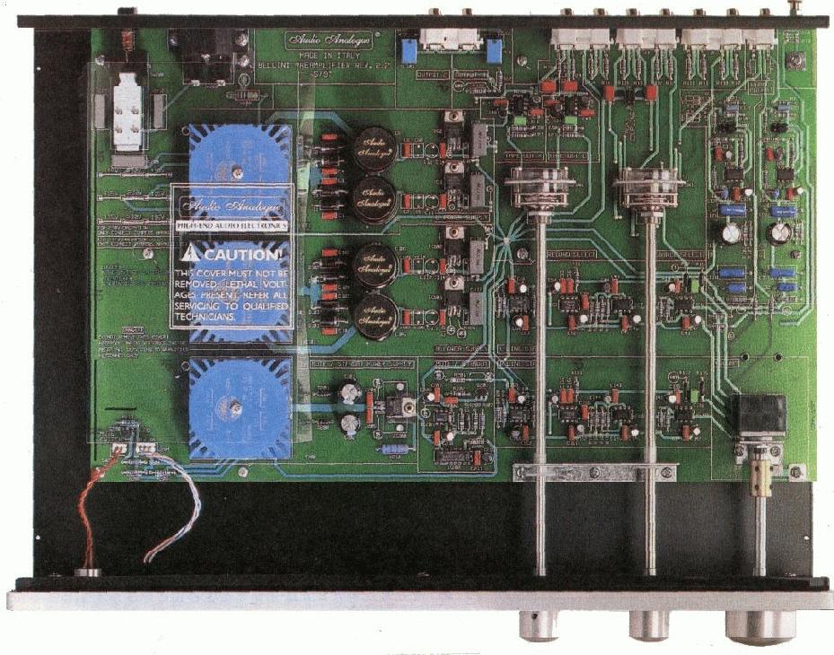 Click
here for an internal view of the Bellini preamplifier
Another interesting "mod" could be the use of the second
pair of RCA outputs for a phase inversion, in order to drive in bridged
mode the Donizetti power amplifier. You can use some of the popular ICs
like the SSM2142. But remember to make some mods into the amplifier too,
or you'll loose the protection circuit !
Click
here for an internal view of the Bellini preamplifier
Another interesting "mod" could be the use of the second
pair of RCA outputs for a phase inversion, in order to drive in bridged
mode the Donizetti power amplifier. You can use some of the popular ICs
like the SSM2142. But remember to make some mods into the amplifier too,
or you'll loose the protection circuit !
Or, you can leave the Bellini as is, and put the same chip into the
Donizetti (it's cheaper, you'll use less cabling !)
Back to the home page