Well, in the previous page we've talk
about
the diagram; now it's time to say something about characteristic of
the...
Audio Analogue PAGANINI CD
player
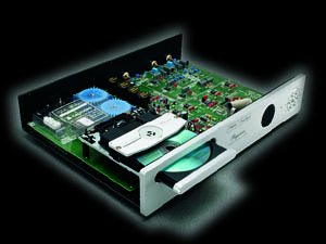
Later we will talk about the CD player's tuning,
and more.
Specifications
Here are the declared (and measured, too!) specs:
DECLARED
|| Prototype MEASURED
Output audio level:
2
Vrms || chR=2.009, chL=1.999, Delta=0.05dB
Output audio impedance: 200 Ohm
Output digital level:
0.5
Vpp || 0.46
Output digital impedance: 75 Ohm
S/N ratio (with no signal): lin.
>90dB,
weighed "A" >100dB || "Lin" 98dB, "A"109dB
Effective resolution:
>15
bit || 15.7 bit
Dynamic
range: >96dB
|| residual noise: 200nV/SQRT(Hz), eq. to 28uVrms (in a
20>20.000
Hz band)
Frequency response:
20Hz
/ 20kHz (+/- 0.5 dB) || 20>20.000 / +/- 0.1dB
Linearity:
+/-
0.5 dB (0dBr / -90dBr) || +/- 0.1 dB (0dBr / -100dBr)
Channels separation:
>90dB
(20Hz / 20kHz) || L>R 100dB, R>L 110dB
THD+N (@1kHz):
<0.03%
from 0dBr to -40dBr, 0.3% @ -60dBr, 3% @ -80dBr
IMD (19kHz +
20kHz): N.D.
|| <96dB@1kHz
DC
offset: N.D.
|| <10mV (remember there is NO capacitor in series at the
output)
Here we have some charts too:
 This
is the THD vs Out level (0dBr is 2Vrms)
This
is the THD vs Out level (0dBr is 2Vrms)
 This
is the frequency response (measured at 0dBr and -10dBr)
This
is the frequency response (measured at 0dBr and -10dBr)
 This
is the channels separation (measured at 0dBr)
This
is the channels separation (measured at 0dBr)
 Linearity
(hor. axis is "out level", vert. axis is "deviation from
ideal" in dB)
Linearity
(hor. axis is "out level", vert. axis is "deviation from
ideal" in dB)
The calibration
procedure
for the CD player
Usually the Paganini is factory calibrated; but if you want to poke
into it yourself, or if you need to change the drive, or if you have
problems
reading some discs (it happens, it happens!), it could be useful to
learn
the calibration procedure.
NOTE: new drives have a tin jumper to prevent ElectroStatic
Discharge on the laser diode. If this is the case, remove it
AFTER
you have connected all the four headers on the pcb.
As you know (have you downloaded the diagram?) in all the Paganini
digital section there is a "half" voltage generator, the output
being pin48 of IC210; this voltage (named VC) is used as a virtual
"zero"
to which all signal are referred; one of these signals is the Focus
Error
Bias, and this must be exactly equal to VC.
Scope of the VR202 trimmer is to tune the FEbias at the same value
of VC.
It is not convenient to measure the latest and to trim the first at
the same value; it is more precise if you read directly the
"difference"
between them.
You need a DVM (at least with 200mV DC fs).
1) remove the tin drop over the "R251" link (between TP209
and TP210) that connects VR201 to pin1 of IC210 (see diagram)
2) put the positive lead of the DVM on TP210 and the negative on
TP209
(range is 200mV DC)
3) Paganini is ON and out of Stand-by
4) adjust VR202 until zero reading on the DVM
5) turn off the player
6) join again the "R251" link
Okay, this was the "easy" part.
Now you need to calibrate the gain of the Focus Coil servo system;
unlucky for you, there is not a "reading on the DVM" to reach;
if the gain is too low simply the drive will refuse to read the CD
after
two or three attempts; if the gain is too high the CD will work, but
all
the servo system will be too much "stiff" trying to follow the
surface of the disc; this in turn will cause a lot of errors to be
generated
by the system. You'll hear a lot of mechanical "noise" in this
situation: the gain is too high!
A "linear" approach to the problem can be this way:
7) rotate VR201 counter clockwise
8) Paganini is ON and out of the Stand-by; tray is OPEN
9) put a disc and push the OPEN/CLOSE switch
10) as you will see, the CD player will refuse to read the disc,
and
the written "disc" will appear on the display
11) pushing twice rapidly the same OPEN/CLOSE switch will force a
new
reading tentative
12) do it several times, every time turning clockwise the FCgain
VR201
trimmer
13) at least you'll find a point where the disc is read!
Now you can connect the usually DVM at TP220 and TP221 (AC mode,
the lowest range, at least 200mV; better if you have a TRUE RMS, but
it's
not strictly necessary).
14) you'll read a value between 70mV and 160mV; this value is not
the
same at the beginning or the end of every disc
15) try several discs, and leave into the ones with the LOWEST
value
read on the DVM
15bis) if you find a disc that the CD won't read, it will be the
LOWEST mV value CD; use it! In this case simply turn even more (very
slowly)
VR201 until it works, than give half turn more for safety. This ends
the
calibration procedure.
16) find the LOWEST value track on this disc (it could be the
first,
the last, or someone in between)
17) While playing this track turn counter clockwise VR201 until the
CD will stop; than start again the procedure beginning at point 11
18) after point 13 give half turn more for safety. Play & test
all the discs you have. Are they all read? Yes? This ends the
calibration
procedure.
Note: DO NOT USE "strange" discs, like
the compilation your best friend made with the Personal Computer: these
discs have an "odd" signal overlapped on the track, or something
similar; well, if you put a scope between TP220 and ground you'll see
it
very high!
Therefore they are not useful for the calibration procedure.
Note (again): if the Paganini reads the disc with strange
noisescoming
from the drive, it means that the gain is too high; reduce it!
The Sony drive
It could be useful to give a look at the drive, and remember that
many Sony units share the same components and/or connections.
CAVEAT! The diagram you find here is not the original, but a
"concept"
version draw by me.
 <--Click
here for the "zipped" poscript file
The KSL-2101ABM is a very common device, and you can easy find it
as
a spare part in your local electronic shop.
If you find other drives with about the same connectors (think to
the
CD-ROM for PC) you can made some tests by substituting the original.
NOTE: never turn the 2k2 trimmer, or the LASER diode will
burn
in a while!
If you want to check for the LASER current (and more), go to the
following
section:
<--Click
here for the "zipped" poscript file
The KSL-2101ABM is a very common device, and you can easy find it
as
a spare part in your local electronic shop.
If you find other drives with about the same connectors (think to
the
CD-ROM for PC) you can made some tests by substituting the original.
NOTE: never turn the 2k2 trimmer, or the LASER diode will
burn
in a while!
If you want to check for the LASER current (and more), go to the
following
section:
Test points
You already know some of the test points: TP209, TP210, TP220, etc.;
one
of the most important to check for proper operation of the Paganini CD
player is TP207: here you'll find the "eye pattern", that
is the Radio Frequency signal recovered from the disc;
you
need a scope for measuring this, and respect to ground you'll read
1Vpp.
This is a typical value for all the Sony chip-set.
Another interesting couple is TP214/TP215: with a Digital
Volt
Meter in DC voltage mode (2Vfs) you'll read 500mV; this in turn is
equivalent
to a current of 50mA in the LASER diode.
Always related to the LASER are the TP211 and TP212;
the first is the voltage developed between Anode and Cathode of the
LASER
diode (usually near 1.91V DC respect to ground, but vary with the age
of
the diode and with the temperature), the second is somewhat related to
the light power emitted by the LASER and received by the photodiode;
here
the voltage is very small: you must read a value near 13mV DC.
As previously stated, TP220 and TP221 are in
parallel
with the Focus Coil, and here you'll read between 70mV and 160mV AC if
you use a standard disc, or between 280mV and 360mV AC if the disc is a
"masterized" one. Note: do NOT use an old "analog"
meter for measuring the Focus coil AC voltage, because sometimes the
reading
can be wrong.
Near IC203 there is a very interesting header, named J207
("TO AA-EC"):
here you have at your disposal +5V (pin1), GROUND (pin6), and three
digital
signals (MNT0>pin3, MNT1>pin4, MNT3>pin5).
Here the mystery is solved: as clearly explained on page 30/31 of
the
CXD2508 data-sheet you can read these data and know when the system
found
an error, what kind of error was, and if it has been completely
corrected
or an interpolation has been used.
AA-EC is Audio Analogue Error Counter,
a never born device useful to understand if some mechanical mods are
useful
or not.
You can read anyway the "status" of these data, even with
a scope or "ANDing" them in the proper way.
Near the DAC also there are lots of data available; these are:
DAC Master Clock (DACMCLK) = TP201
Left & Right Clock (LRCK) = TP202
Serial Data (PCMD) = TP203
Serial Clock (BCK) = TP204
Negated Emphasys (NEMPH) = TP205
Mute R & L (MUT2) = TP206
With these data you can decide to use your own new DAC, mounting
it
on a little PCB.
I remember you the new Audio Analogue MAESTRO CD player, where all
is similar to the Paganini except the DAC.
In the power supply section you can measure the DC voltage on the
collector
of Q403 (the power darlington): you'll find +20V in STOP mode,
+18V
in PLAY mode, +15V while pressing the FWD or REV buttons, 0V in
STAND-BY
mode.
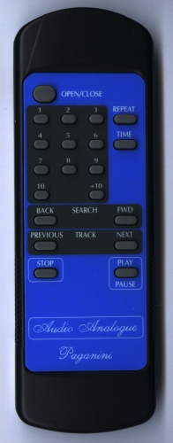
The Remote Control
The Remote Control used in the Paganini is a custom
model,
made for us by the
TOP-UP
INDUSTRY CORPORATION
in TAIWAN.
Using it, you'll have more functions than the front panel, but even
in this case not all the functions are implemented.
You can try what are the excepted command playing with Rows and
Columns
around the U1 chip into the RC unit.
 <--CLICK
here for the electric diagram of the R.C. (141k GIF format)
It works with two AAA size cells (3Vdc), and signals are received
very
far from the CD player until you are in front of the receiver.
Problems arise when you have an angle of more than 45 degree in
whatever
direction.
<--CLICK
here for the electric diagram of the R.C. (141k GIF format)
It works with two AAA size cells (3Vdc), and signals are received
very
far from the CD player until you are in front of the receiver.
Problems arise when you have an angle of more than 45 degree in
whatever
direction.
Hints & Tricks
It is quite oblivious that some simple mods are possible, e.g. change
of
the loading motor's speed (tune the R226/R227 ratio); but for some deep
analysis you need some test discs.
I can recommend some:
Discs with & without physical errors for testing servo
circuits
and errors correction capability:
Philips
SBC
426/426A (2 discs)
Grundig
72008-376.00
(2 discs)
Panasonic
CDT
016
Pierre Verany
PV.788031/PV.788032
(2 discs)
Sony YEDS
3-702-529-01
Konig CD
5441
Discs with standard signals for measuring THD and more:
Konig CD
5443
CBS (Standard Test Disc)
CD-1
EIAJ (Standard Test Disc)
CD-1
(YGDS 13)
Japan Audio Society Test Disc CD-1 (YDDS 2)
Philips
Test
Sample 3 (410 055-2)
Technics CD
Test Disc 1 (SH-CD001)
Sony
YEDS
3-703-811-01
Sony
YEDS
3-702-101-01
Sony Test
CD Type 3 (YEDS-7)
Sony Test
CD Type ? (YEDS-18) 3-702-101-01
Denon
GES-9092
Denon
38C39-7147
DHFI
410
741-2
Divox
CDXUE-84
Mozart editrice (Terni- Italy)
CD
MZT 10001-2 (warning: in my disc there is a glitch in track 10 at time
24S)
Stereophile TEST CD2
STPH
004-2
Stereophile TEST CD3
STPH
006-2
Surely there will be many test discs on the market; a simple search in
the WEB with the words "+test +disc" gave me many pages like
these:
http://www.digital-recordings.com/cdcheck/cdcheck.html
http://www.abex.com.sg/cd.htm
http://www.tmd.co.jp/eng/tmddisk1.htm
http://www.ee.washington.edu/conselec/CE/reports/Group.3/cbs_cd1.html
When you'll have a sufficient number of test discs, you can start
an
interesting adventure over the .....
Tuning of the time constants
Yes, the Paganini (like ALL the CD players) is full of servo circuits,
and this means that there are some time constants (in other words: some
RC groups) that needs to be "tailored" in order to obtain best
performances even with "horror" discs.
We've made of our best, but if you have time for build the "AA-EC
device" you can play with different RC values and see if the errors
grows or not.
Here a list of components to play with:
C202
R201,C203
C204
R219, R220, C222, C223
C227
C225, R222, R221, C224
C216
C213, C214
C215
C238, R238
R240, C239
C240, R241
C241, R242, C242, R243
For a tuning procedure you need a dual channel FFT analyzer (e.g.:
HP3562A)
and a good knowledge of how a servo circuit works (Hint: trim
the
gain up to a "critical Q" response).
You find some info (by Sony)
clicking
here (thanks, Santo); unluckily is not a complete procedure, but is
a good starting point.
Some last words
It remains to talk about the "test" condition: something happens
if you power the Paganini while pressing the FWD button: the system
seems
to enter in a "test" mode, but nothing of importantance really
happens.
Nevertheless there is a "test" mode in IC301 also: you have
to tie down pin24 and try to power the Paganini.
Sony is quite miserly about this kind of information, so I cannot
help
you; try by yourself!
Another important question is the output resistor R7(R107): in
some
recent productions I've seen that this resistor has been substitute
with
a "zero" Ohm resistor (a piece of wire, in other words).
Well, I absolutely disagree with this procedure; it's always a good
rule to be concerned with capacitive loads (e.g.: long & strange
cables,
etc.) with a series resistor, and with this no "ringing" in the
square wave corners are possible.
Not only: if the zero Ohm resistor is used, the Paganini spend all
his "Stand-by" time with IC1 (IC101) shorted to ground; nothing
of really "dramatic" happens, but the internal temperature balance
of the chip will not be the best at the wake-up, and some minutes will
needed for coming back in a normal steady state situation.
Listen carefully: open the Paganini and take a look inside: if
you
don't find the resistors (they are WELWYN RC55Y, the colour is black)
eradicate
the fakes and put real resistors!
It could be useful to have a list of the material needed for the
Paganini:
here you find the provisional document
in Word (zipped) format.
At the end of this long page I suggest to read this useful site:
the Sci.Electronics.Repair
FAQ under the voice CD Player.
I hope you have found these page interesting; please let
me know your remarks, and do not hesitate to contact me for
whatever
question you should have.
Back to the home page
 <--CLICK
here for the electric diagram of the R.C. (141k GIF format)
<--CLICK
here for the electric diagram of the R.C. (141k GIF format)