So it's (at least!) time to talk about the....
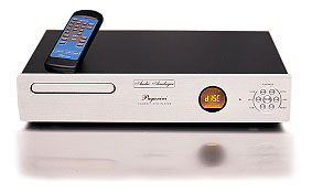
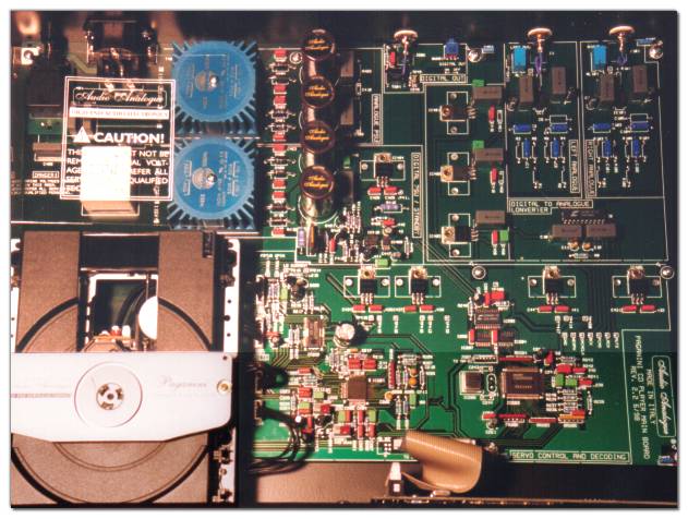
Audio Analogue PAGANINI CDplayer
However, talking about the Paganini is quite the same
that talking about the Maestro, the "higher price" CD player of the Audio
Analogue: in fact about 90% of the work (the mechanics, the servo circuit,
the DSP, the display, in other words the whole digital section; plus the
case, the front panel, etc.) is exactly the same in the two CD players.
The only relevant differences are in the DAC section (Crystal 24 bit and
op-amp post filtering in the Paganini, Burr Brown 24 bit and discrete components
in the Maestro) and in the (one more) transformer for the analog power
supply.
These differences, In My Opinion,
lead to a factory cost of about 20% higher for the Maestro.
Oh, well, there is another difference too: the Paganini has
been designed by the two original designers and founders of the Audio Analogue:
Mr.
Santo Pratticò and me (Federico Paoletti)!
Well, let us now
have a look at the Paganini CDP; this being a very complex project
I ask you to relax before proceeding.
.......
Are you ready? OK, let's GO.
The drive mechanism
First of all, you need a drive, and the world is divided in two guidelines:
the Sony and the Philips.
Yes, I know there are other interesting brands like Teac and so on, but
if you need to start a design buying a low quantity of pieces you have
only the former choice.
The relevant fact is that with the Sony you have a complete chip-set that
needs only to be wired, with the Philips you need some form of DSP to be
programmed with some exotic language in order to obtain some stupid functions
(e.g. press "open" and the tray does it).
So we made some tests, and we decided for Sony; we made only an aesthetic
alteration: the plastic bridge that support the magnetic centering mechanism
has
been replaced by an aluminium one, with the Audio Analogue logo printed
over it (someone says this is the reason the Paganini plays better).
The selected drive is a Sony KSL-2101ABM with the following items
"on-board":
LOADING motor
SPINDLE motor
SLED motor
TRACKING SERVO coil
FOCUS coil
LASER diode
CURRENT LASER diode
RF diode
TRACKING diode
DISC-IN / DISC-OUT switches
LIMIT switch
All these signals are brought out with four connectors, named as:
J201, white colour, 8 wires (RF diode, TRACKING diode)
J202, red colour, 8 wires (LASER diode,
CURRENT LASER diode, TRACKING SERVO coil, FOCUS coil)
J203, white colour, 6 wires (SPINDLE motor, SLED motor,
LIMIT switch)
J204, white colour, 5 wires (DISC-IN / DISC-OUT switches,
LOADING motor)
We used the following Sony chip-set in the CD:
CXA1782Q (RF Signal Processing Servo Amplifier for CD players)
This takes care of the LASER power and positioning; driving the diode,
the coils and some motors; it also recover the Radio Frequency signal to
be processed by the DSP.
CXD2508Q (CD Digital Signal Processor)
It reads and demodulates the RF signal, recovering various signals from
the EFM modulation stream; it buffers data into a FIFO memory creating
the SPINDLE motor signal; it talks with the system controller; gives as
output the signals for the DAC.
CXP1042Q (System Controller for Compact Disc Players)
It is the interface between the user and the rest of the circuits, via
the keyboard and the display.
Ancillary chip is the Rohm BA6395FP, nothing but a power interface
driving coils and motors.
Some of the signals needed for the mechanics are created by IC201 -
CXA1782Q (Focus and Tracking coils, Sled and Spindle motors); others are
generated by IC203 - CXD2508Q (the Forward and the Reverse controls, and
some enable/disable data).
The diagram
Yes, you now MUST download the whole diagram
of the Paganini CD player! As usual, it's a poscript zipped diagram;
once you've "unzipped" it you need some form of poscript reader, e.g. GSVIEW32.exe.
Or simply send it to a poscript printer.
The digital circuits
The Sony CXA1782Q is the chip that reads the quadrant photodiode (ABCD)
and the tracking error photodiode (EF), and from these signals extracts
the RF signal (that contains the audio data) and a lot of other signals
that are used locally for reading the CD or used by the DSP (IC203).
 <--Here
the PDF (762k)
Some of the local signals are the Focus Error (FEO), the Tracking Error
(TEO), the Center Voltage (it is half of the power supply), the Automatic
Power Control (APO), the Sled Motor (SLO); other signals are present on
a serial bus connected to the DSP (e.g. pins 19 to 25).
Some errors on the component's value are present in the Sony data-sheet
(e.g.
C226 has a real value of 2n2, not 22nF; as well as C224 that is 2n2 again
and not 47pF).
<--Here
the PDF (762k)
Some of the local signals are the Focus Error (FEO), the Tracking Error
(TEO), the Center Voltage (it is half of the power supply), the Automatic
Power Control (APO), the Sled Motor (SLO); other signals are present on
a serial bus connected to the DSP (e.g. pins 19 to 25).
Some errors on the component's value are present in the Sony data-sheet
(e.g.
C226 has a real value of 2n2, not 22nF; as well as C224 that is 2n2 again
and not 47pF).
The Rohm BA6395FP is a 5 channel driver and V/I converter specified
for CD player motors and actuators; we didn't use the internal regulator
(pin 5 and 6); the voltage at pin 19 fixes the disc loading/unloading speed
(the higher the voltage, the faster the movement).
 <--Here
the PDF (187k)
The signals amplified from this chip are: SLED, SPINDLE and LOADING motors;
TRACKING and FOCUS coils.
<--Here
the PDF (187k)
The signals amplified from this chip are: SLED, SPINDLE and LOADING motors;
TRACKING and FOCUS coils.
The Sony CXD2508Q is the DSP; the main task is to read the RF signal
and to extract (Eight to Fourteen Modulation) some
important data.
 <--Here
the PDF (604k)
These are:
<--Here
the PDF (604k)
These are:
-
the CHANNEL CLOCK (performed by an internal PLL circuit);
-
the SUBCODE DATA (P,R,S,T,U,V,W at pin 2, Q at pin 4): the P subcode
is a flag used for the beginning and the end of the audio signal, the Q
subcode is used by the CPU for display utility;
-
the DAC DATA (LRCK, BCK, PCMD, EMPH, DACMCLK)
-
the ERROR DATA (MNT0, MNT1 and MNT3);
-
the SPINDLE motor velocity DATA (is obtained storing data into a
16k RAM FIFO)
There is also a digital filter and a D/A 1bit converter in this chip, but
they aren't used.
Some of the above signals are used by the SPDIF interface chip (Crystal
CS8402A), a biphase-mark encoder whose output signal is activated by SW201
on the rear panel.
 <--Here
the PDF (307k)
This chip is used in "Consumer" mode: data are LSB justified, 16 bit, 44.1
kHz; output characteristics are 0.5 Vpp / 75 Ohm via the isolation transformer
T201
<--Here
the PDF (307k)
This chip is used in "Consumer" mode: data are LSB justified, 16 bit, 44.1
kHz; output characteristics are 0.5 Vpp / 75 Ohm via the isolation transformer
T201
The end of the digital chain is the Sony
CXP1042Q (click for the 561k PDF), a 4 bit single chip microcomputer
that incorporates programs for CD operations. The job of this chip is to
interface between the keyboard, the IR remote control, the display and
the rest of the CD player.
Not all the possible functions are implemented in the Paganini, at least
on the front panel operation; more freedom is left to the owner using the
infrared remote control.
About this latter, the format is NEC and the code is AACD (Audio
Analogue
Compact Disc).
Over the little PCB that supports IC301, in the back of the front panel,
there is the LCD display unit and the IR receiver (IC303).
Backlighting for the display is obtained with four SMD Hewlett-Packard
LEDs.
The converter
DAC DATA from IC203 are also used for driving the CS4390 24bit Crystal
D/A converter.
We consider this chip one of the "best sound" available on the market at
the moment of designing this CD player (about 1998).
The ability of reaching 96kHz clock data is worth nothing if you don't
have it! What is important is the true linearity and the dynamic range,
in order to obtain a value as close as possible to the theoretical 16bit
limit from the disc you're playing.
In this sense it's a good rule to use a 24bit DAC, even if you're dealing
with 16bit stream.
So the Crystal CS4390 was one of the first chips to reach this limit, and
it was suited over the maximum clock frequency used in domestic appliances:
the 48kHz of the DAT recorder.
 <--Here
the PDF (978k)
Some interesting features of this chip are the 97dB THD+N, low clock jitter
sensitivity, Delta/Sigma 1bit DAC, "in-chip" switched-capacitor low pass
analog filter. This latter is a linear phase design, and a great care must
be used to the design of the external filtering system: although a Bessel
type should seems the best choice, extensive tests show that a "maximally-flat"
Butterworth filter reduces the error at 20khz with negligible phase deviation
in the audio band.
<--Here
the PDF (978k)
Some interesting features of this chip are the 97dB THD+N, low clock jitter
sensitivity, Delta/Sigma 1bit DAC, "in-chip" switched-capacitor low pass
analog filter. This latter is a linear phase design, and a great care must
be used to the design of the external filtering system: although a Bessel
type should seems the best choice, extensive tests show that a "maximally-flat"
Butterworth filter reduces the error at 20khz with negligible phase deviation
in the audio band.
 <--Here
the PDF (73k)
<--Here
the PDF (73k)
Selecting the output operational amplifier is not a simple task; we
tested a very nice operational amplifier like the Analog
Devices AD797 (it is defined as "Ultralow distortion, ultralow noise"),
and we found it very promising as "first of the class"; unfortunately it
was marginally stable, so we turned to the ubiquitous Texas TLE2071CP,
as used in the BELLINI preamplifier.
Anyway you'll notice the presence of C5/C105 (defined as "optional" on
the diagram): it was foreseen for the use of the AD797.
There is a resistor in series with the signal (more on this later), needed
for damping capacitive loads and for not short-circuiting the operational
amplifier when the muting relay RL1/RL101 is activated.
The power supply
It remains to talk about the power supply: this is not esoteric, but employ
some simple rules for avoiding cross-talk between digital and analog circuits.
In detail: the main power supply is filtered with FL401, then controlled
by SW401 general switch, located in the rear; circuit signal ground (SGND)
is connected to the earth (TP401) via the 10 Ohm resistor R401, avoiding
ground loops with other electronics. This resistor has in parallel four
capacitors (C454 to C457): these act as short circuit for high frequencies
bringing the SGND to earth potential for non-audio signals.
Two toroidal TALEMA transformers supply current to circuits: T401 for the
analog side (split supply mode) and T402 for the digital circuits (secondary
windings are in parallel).
Conventional three terminals ICs are used, and while all the analog section
is always "on" (at least when the back mains switch is on too!), the digital
section is divided in two: IC404 supply power to VSTBY, and is always "on";
all the remaining supply ICs are powered only if the CD player is not in
Stand-By condition.
The Stand-By is one of the "bullet" switches on the front panel: pressing
it pulls down pin2 of IC409 (NE555 timer) and this toggle the out (pin
3) for a time RC (R406/C443); this in turn force a change of state at the
output of IC410A (the LED goes off and the darlington Q403 starts conducting,
powering the rest of the digital circuit). During the first power-up IC410A
is forced with "Q" low by the pair R407/C444.
Well, this page is growing too much!
Jump to the next page, where you'll know more
about the Paganini CD player, or come Back
to the home page if you're annoyed.